Moteino, RFM12PiV2 & Rioja (Raspberry Pi no OpenStack)
2015-04-26
Machine-translated from English. Read the English original
Así que, por fin, he tenido tiempo de iniciar mi largamente esperado proyecto de domótica – mi excusa para jugar con todo lo del “Internet de las Cosas” (IoT). A largo plazo, me gustaría involucrar a mi escuela local – llevando el IoT a la comunidad. Dado que mi trabajo diario requiere explorar muchas tecnologías divertidas, protocolos y python (hacker no programador) todo en nombre de la automatización de centros de datos (también conocido como computación en la nube para los tipos de marketing allá afuera), voy a aprovechar estas habilidades para crear un ecosistema de domótica robusto. Los DL360s y los iLOs serán reemplazados por Raspberry Pis y Arduinos.
Hay muchos blogs excelentes en internet que me han inspirado, como JeeLabs , LowPowerLabs y la esquina de Martin en la web. ¡Estos chicos son expertos! Por favor, consulten estos sitios si desean construir el suyo propio. Yo estoy construyendo por el sake de aprender; ya existen sistemas fantásticos listos para usar. Este blog simplemente presentará los descubrimientos que creo que pueden interesar a otros mientras estoy en mi viaje…
Jugando con comunicaciones RF de bajo consumo
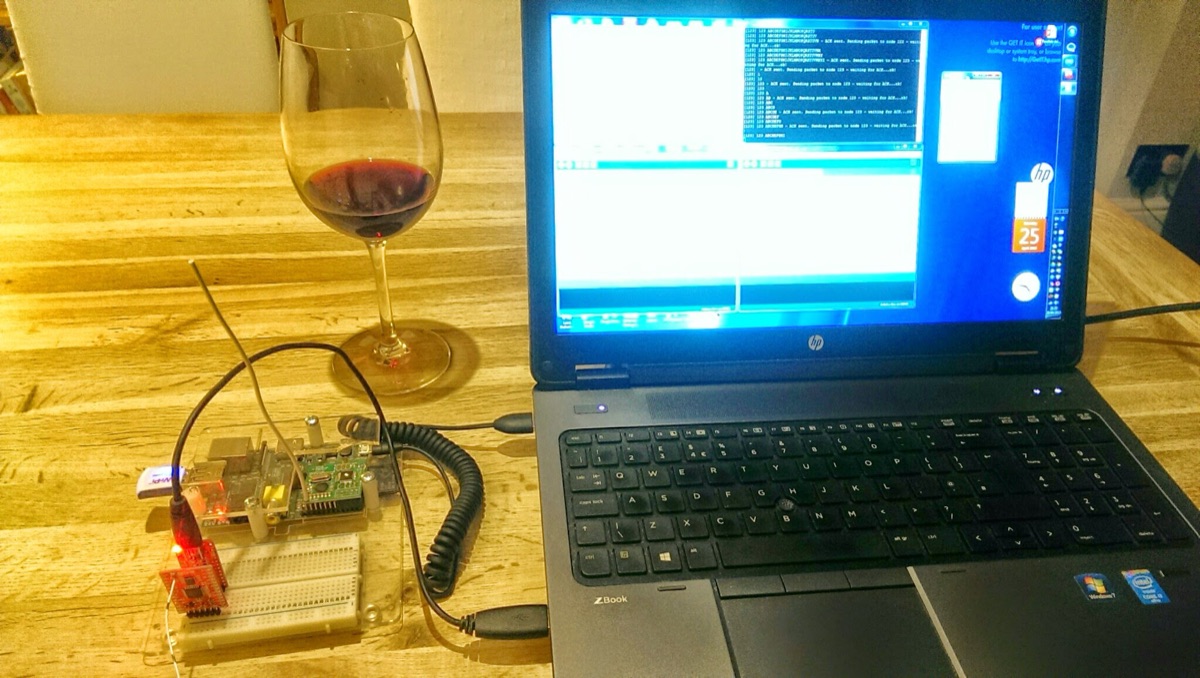
Si se preguntan por qué no me limito simplemente al WiFi para las comunicaciones, la respuesta es simplemente potencia y alcance. Los módulos WiFi son hambrientos de energía en comparación con los dispositivos RF más simples. No todos los dispositivos que se conectarán a internet estarán cerca de una fuente de alimentación, por lo que será necesario alimentarlos con baterías – por ejemplo, monitores de plantas, sensores de temperatura remotos, etc. En última instancia, estos dispositivos con batería enviarán su información a internet a través de un gateway Raspberry Pi (RPi). El RPi tendrá tanto conectividad a internet como conectividad RF.
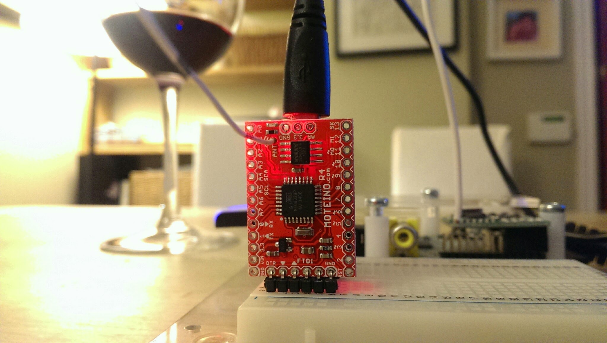
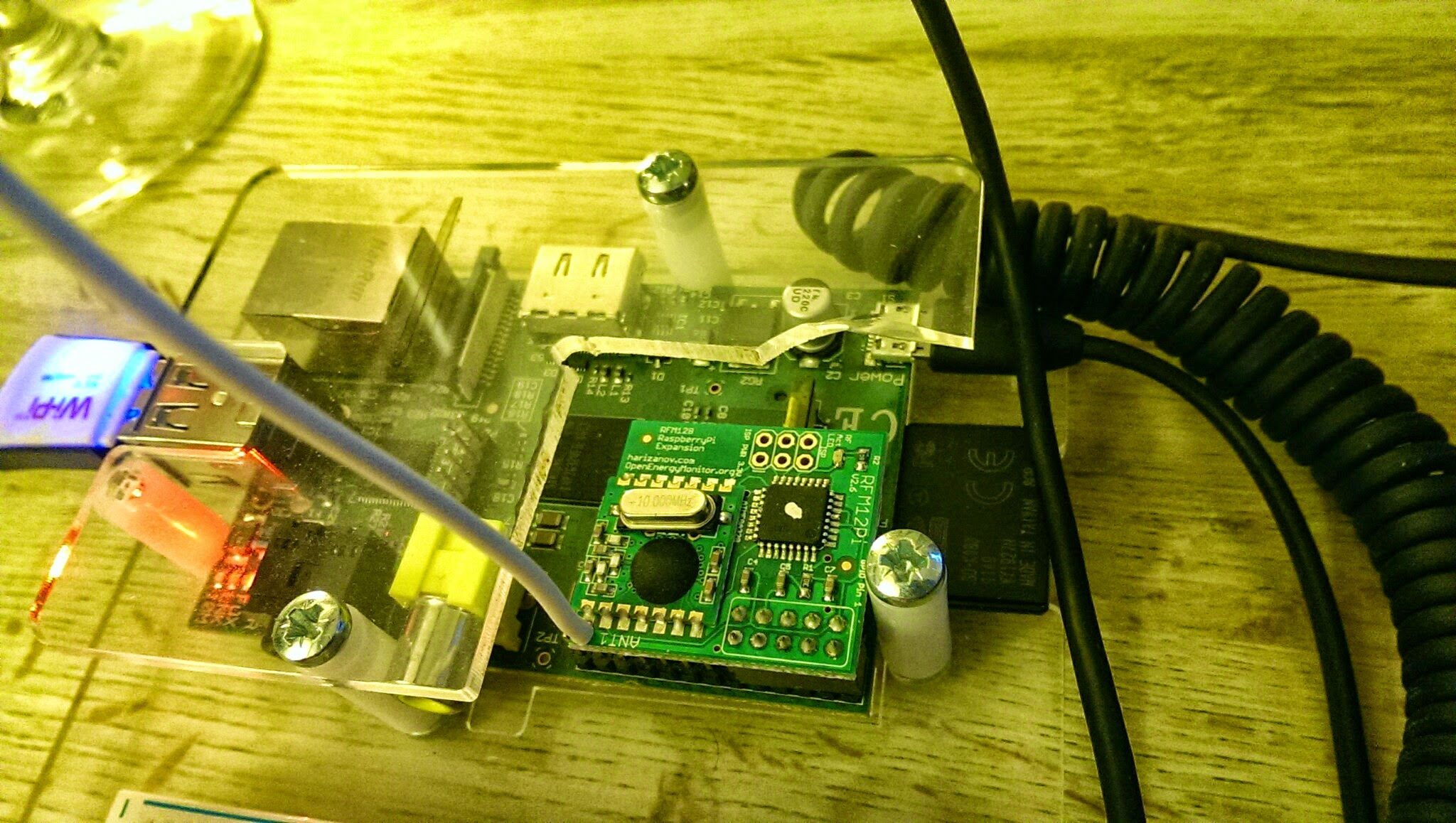
El primer desafío que tuve fue evaluar algunos dispositivos RF listos para usar de bajo costo, que incluían un par de Moteinos (estos son superbios), de Felix en LowPowerLabs.com y el RFM12PiV2 del proyecto OpenEnergyMonitor. Este dispositivo se conecta a la Raspberry Pi y será el gateway a internet para todos mis dispositivos IOT basados en RF.
Como elegí dispositivos RF de dos proyectos diferentes, necesitan algunos ajustes para que hablen correctamente entre sí, y eso es lo que cubrirá el resto de este blog.
Lo que estos dispositivos tienen en común es que ambos utilizan la plataforma de desarrollo compatible con Arduino basada en el chip ATMega328. Como resultado, ambos pueden ser programados usando el IDE de Arduino. Los dispositivos también tienen una placa hija integrada que contiene el transceptor HopeRF RFM12B.
Difieren en que ambos ejecutan programas diferentes (también conocidos como sketches en el mundo de Arduino) y sus relojes de hardware también han sido arquitectados ligeramente de manera diferente. El Moteino utiliza una señal de reloj externa de 16Mhz, mientras que el RFM12PiV2 utiliza el reloj interno de 8Mhz que está integrado en el ATMega328. Esta última pieza de información es vital al sincronizar la transmisión entre los dispositivos.
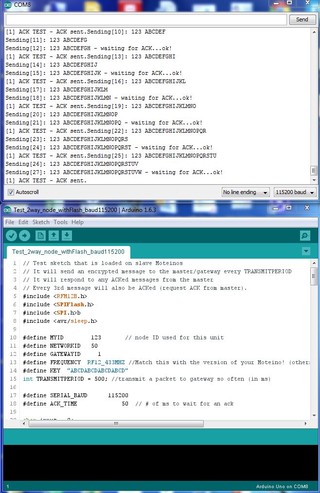
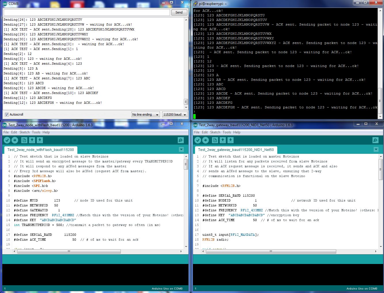
Decidí usar los sketches de prueba de los Moteinos ubicados aquí – Nodo y Gateway solo cambiando la dirección y la velocidad de baudios como se puede ver a continuación :
Sketch del Nodo
// Test sketch that is loaded on slave Moteinos
// It will send an encrypted message to the master/gateway every TRANSMITPERIOD
// It will respond to any ACKed messages from the master
// Every 3rd message will also be ACKed (request ACK from master).
#include <RFM12B.h>
#include <SPIFlash.h>
#include <SPI.h>b
#include <avr/sleep.h>

#define MYID 123 // node ID used for this unit
#define NETWORKID 50
#define GATEWAYID 1
#define FREQUENCY RF12_433MHZ //Match this with the version of your Moteino! (others: RF12_433MHZ, RF12_915MHZ)
#define KEY "ABCDABCDABCDABCD"
int TRANSMITPERIOD = 500; //transmit a packet to gateway so often (in ms)

#define SERIAL_BAUD 115200
#define ACK_TIME 50 // # of ms to wait for an ack

char input = 0;
RFM12B radio;
SPIFlash flash(8, 0xEF30); //EF30 for Windbond 4mbit flash
boolean requestACK = false;
byte sendSize=0;
char payload[] = "123 ABCDEFGHIJKLMNOPQRSTUVWXYZ";

void setup()
{
Serial.begin(SERIAL_BAUD);
radio.Initialize(MYID, FREQUENCY, NETWORKID, 0);
radio.Encrypt((byte*)KEY);
char buff[50];
sprintf(buff, "Transmitting at %d Mhz...", FREQUENCY == RF12_433MHZ ? 433 : FREQUENCY== RF12_868MHZ ? 868 : 915);
Serial.println(buff);
if (flash.initialize())
Serial.println("SPI Flash Init OK!");
else
Serial.println("SPI Flash Init FAIL! (is chip present?)");
}

long lastPeriod = -1;
void loop()
{
//process any serial input
if (Serial.available() > 0) {
input = Serial.read();
if (input >= 48 && input <= 57) //[0,9]
{
TRANSMITPERIOD = 100 * (input-48);
if (TRANSMITPERIOD == 0) TRANSMITPERIOD = 1000;
Serial.print("\nChanging delay to ");
Serial.print(TRANSMITPERIOD);
Serial.println("ms\n");
}
else if (input == 'd') //d=dump flash area
{
Serial.println("Flash content:");
int counter = 0;

while(counter<=256){
Serial.print(flash.readByte(counter++), HEX);
Serial.print('.');
}
while(flash.busy());
Serial.println();
}
else if (input == 'e')
{
Serial.print("Erasing Flash chip ... ");
flash.chipErase();
while(flash.busy());
Serial.println("DONE");
}
else if (input == 'i')
{
Serial.print("DeviceID: ");
Serial.println(flash.readDeviceId(), HEX);
}
}

//check for any received packets
if (radio.ReceiveComplete())
{
if (radio.CRCPass())
{
Serial.print('[');Serial.print(radio.GetSender(), DEC);Serial.print("] ");
for (byte i = 0; i < *radio.DataLen; i++)
Serial.print((char)radio.Data[i]);

if (radio.ACKRequested())
{
radio.SendACK();
Serial.print(" - ACK sent.");
}
Blink(9,5);
}
}

int currPeriod = millis()/TRANSMITPERIOD;
if (currPeriod != lastPeriod)
{
lastPeriod=currPeriod;
//Send data periodically to GATEWAY
Serial.print("Sending[");
Serial.print(sendSize);
Serial.print("]: ");
for(byte i = 0; i < sendSize; i++)
Serial.print((char)payload[i]);

requestACK = ((sendSize % 3) == 0); //request ACK every 3rd xmission
radio.Send(GATEWAYID, payload, sendSize, requestACK);
if (requestACK)
{
Serial.print(" - waiting for ACK...");
if (waitForAck(GATEWAYID)) Serial.print("ok!");
else Serial.print("nothing...");
}

sendSize = (sendSize + 1) % 31;
Serial.println();
Blink(9,5);
}
//else { Serial.print("currPeriod = "); Serial.print(currPeriod); Serial.print(" lastPeriod = "); Serial.println(lastPeriod); }
}

// wait a few milliseconds for proper ACK to me, return true if indeed received
static bool waitForAck(byte theNodeID) {
long now = millis();
while (millis() - now <= ACK_TIME) {
if (radio.ACKReceived(theNodeID))
return true;
}
return false;
}

void Blink(byte PIN, int DELAY_MS)
{
pinMode(PIN, OUTPUT);
digitalWrite(PIN,HIGH);
delay(DELAY_MS);
digitalWrite(PIN,LOW);
}
Sketch del Gateway
// Test sketch that is loaded on master Moteinos
// It will listen for any packets received from slave Moteinos
// If an ACK request message is received, it sends and ACK and also
// sends an ACKed message to the slave, ensuring that 2-way
// communication is functional on the slave Moteino

#include <RFM12B.h>

#define SERIAL_BAUD 115200
#define NODEID 1 // network ID used for this unit
#define NETWORKID 50
#define FREQUENCY RF12_433MHZ //Match this with the version of your Moteino! (others: RF12_433MHZ, RF12_915MHZ)
#define KEY "ABCDABCDABCDABCD" //encryption key
#define ACK_TIME 50 // # of ms to wait for an ack
uint8_t input[RF12_MAXDATA];
RFM12B radio;

void setup()
{
pinMode(9, OUTPUT);
radio.Initialize(NODEID, FREQUENCY, NETWORKID);
radio.Encrypt((byte*)KEY);
Serial.begin(SERIAL_BAUD);
char buff[50];
sprintf(buff, "Listening at %d Mhz...", FREQUENCY == RF12_433MHZ ? 433 : FREQUENCY== RF12_868MHZ ? 868 : 915);
Serial.println(buff);
}

byte recvCount = 0;

void loop()
{
if (radio.ReceiveComplete())
{
if (radio.CRCPass())
{
digitalWrite(9,1);
Serial.print('[');Serial.print(radio.GetSender(), DEC);Serial.print("] ");
for (byte i = 0; i < *radio.DataLen; i++)
Serial.print((char)radio.Data[i]);

if (radio.ACKRequested())
{
byte theNodeID = radio.GetSender();
radio.SendACK();
//when a node requests an ACK, respond to the ACK and also send a packet requesting an ACK
//This way both TX/RX NODE functions are tested on 1 end at the GATEWAY
Serial.print(" - ACK sent. Sending packet to node ");
Serial.print(theNodeID);
delay(10);
radio.Send(theNodeID, "ACK TEST", 8, true);
Serial.print(" - waiting for ACK...");
if (waitForAck(theNodeID)) Serial.print("ok!");
else Serial.print("nothing...");
}
delay(5);
digitalWrite(9,0);
}
else Serial.print("BAD-CRC");

Serial.println();
}
}

// wait a few milliseconds for proper ACK to me, return true if indeed received
static bool waitForAck(byte theNodeID) {
long now = millis();
while (millis() - now <= ACK_TIME) {
if (radio.ACKReceived(theNodeID))
return true;
}
return false;
}
Descargando el sketch al Moteino
Esto es directo conectando el Moteino directamente a una PC que ejecute el Arduino IDE y usando el proceso estándar de Arduino. Estos dispositivos también tienen una capacidad de programación inalámbrica muy útil que se cubre aquí.
Descargando el sketch al RFM12PiV2 (usando la Raspberry Pi)
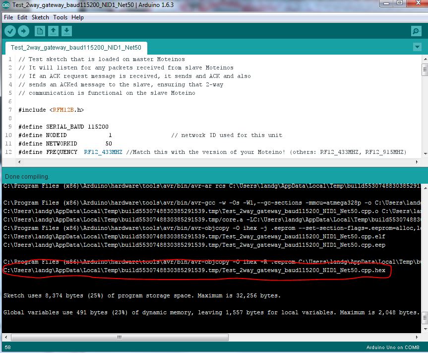
Este proceso es un poco más complicado. Necesitamos compilar el sketch del gateway usando el Arduino IDE primero y luego localizar el archivo bin compilado.
Habilite la salida detallada en las preferencias del Arduino IDE como se muestra a continuación :
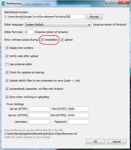
Ahora, cuando compile el sketch, la ventana de salida le dará la ubicación del archivo compilado que necesitará transferir a la Raspberry Pi.
Asegúrese de que el puerto serial en la Raspberry Pi haya sido habilitado como se detalla aquí.
La última pieza de este rompecabezas – Cómo subir nuevo código desde la Raspberry Pi al RFM12PiV2 – ya ha sido documentada aquí pero también se delineará nuevamente a continuación :
$ sudo apt-get update
$ sudo apt-get install -y arduino python-dev python-rpi.gpio
$ git clone https://github.com/mharizanov/avrdude-rpi.git
$ cd avrdude-rpi
$ sudo cp autoreset /usr/bin
$ sudo cp avrdude-autoreset /usr/bin
$ sudo mv /usr/bin/avrdude /usr/bin/avrdude-original
$ sudo ln -s /usr/bin/avrdude-autoreset /usr/bin/avrdude
# Change to the directory where the binary file has been copied
$ avrdude -v  -c arduino -p ATMEGA328P -P /dev/ttyAMA0 -b 38400 -U flash:w:<Enter Filename Here and remove arrow brackets>
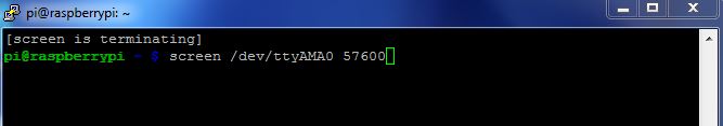
Finalmente, use su herramienta de elección para leer el puerto serial en la Raspberry Pi – he optado por screen. A largo plazo usaré un script de python.
NOTA Recuerde la diferencia en las velocidades de reloj – eso entra en juego ahora. A pesar de que ambos sketches establecen la velocidad de baudios en 115200, al conectarse al RFM12PiV2 que se ejecuta a la mitad de la velocidad de reloj, 8MHz en lugar de 16MHz, es necesario establecer la velocidad de baudios en 57600 y NO 115200.
Ahora deberías ver algo como esto
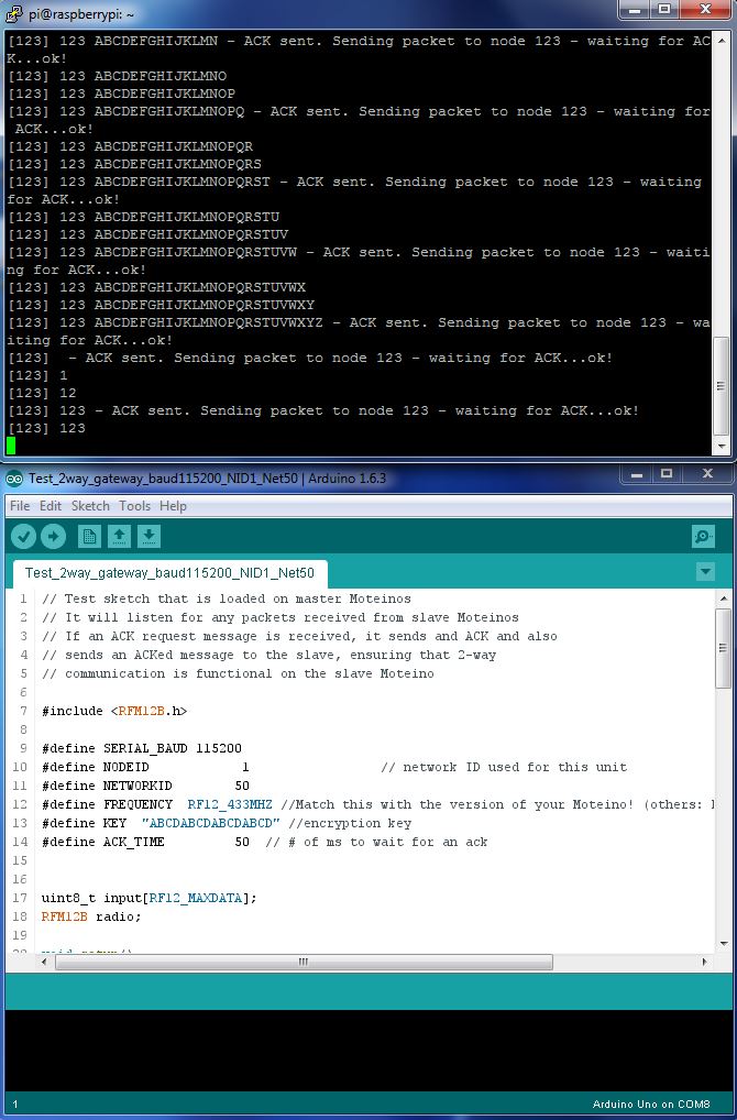
Poniéndolo todo junto te dará un sistema de comunicación base funcional de Moteino a RFM12PiV2.
¡Taaaa – Daaaa!
Lamentablemente, aparentemente el módulo RFM12B está ahora fuera de producción, así que tendré que hacer todo esto de nuevo con el RFM69 o tal vez intente estos
🙂
Originally published on allthingscloud.eu (2015-04-26).