Moteino、RFM12PiV2 & リオハ(Raspberry PiはOpenStackではありません)
2015-04-26
Machine-translated from English. Read the English original
ようやく、長年待ち望んでいたホームオートメーションプロジェクトを始動させる時間ができました – これは「モノのインターネット」(IoT)を遊び倒すための言い訳です。長期的には、地元の学校を巻き込んで、IoTをコミュニティに広げていきたいと考えています。私の日頃の業務では、データセンターの自動化(つまり、マーケティング担当者の間では「クラウドコンピューティング」と呼ばれているもの)のために、多くの面白い技術、プロトコル、そしてPython(ハッカーでありプログラマーではありません)をいじる必要があり、これらのスキルを活用して堅牢なホームオートメーションエコシステムを構築しようと思います。DL360やiLOは、Raspberry PiとArduinoに置き換えられます。
インターネット上には、私にインスピレーションを与えてくれた素晴らしいブログがいくつかあります。例えば、JeeLabs、LowPowerLabs、そしてMartin’s corner on the webなどです。これらの人々は専門家です!ご自身で構築したい場合は、これらのサイトを参照してください。私は学習のために構築しているだけで、すでに素晴らしい完成済みのシステムが存在します。このブログでは、私の旅の途中で他の人が興味を持つかもしれない発見を紹介するだけです…
低電力RF通信を遊ぶ
なぜWiFiではなく通信に他のものを使うのかという疑問があるかもしれませんが、答えは単純に「電力」と「範囲」です!WiFiモジュールは、よりシンプルなRFデバイスと比較して電力を多く消費します。インターネットに接続されるすべてのデバイスが電源の近くに配置されているわけではないため、バッテリーで動作させる必要があります。例えば、植物モニタや遠隔温度センサーなどです。最終的に、これらのバッテリー駆動デバイスは、ゲートウェイとなるRaspberry Pi(RPi)を介してインターネットに情報を送信します。RPiにはインターネット接続とRF接続の両方が備わります。
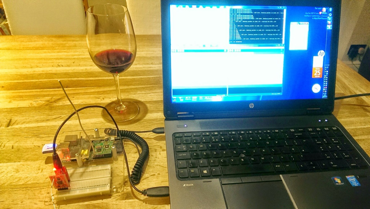
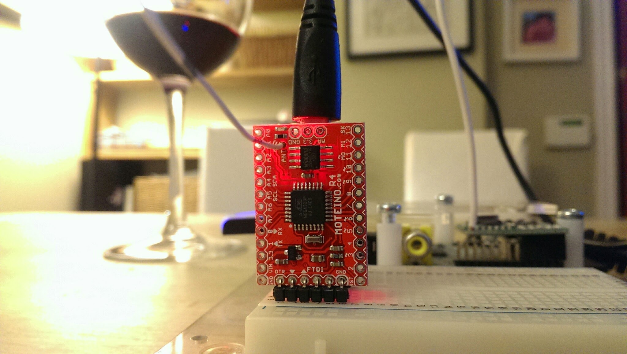
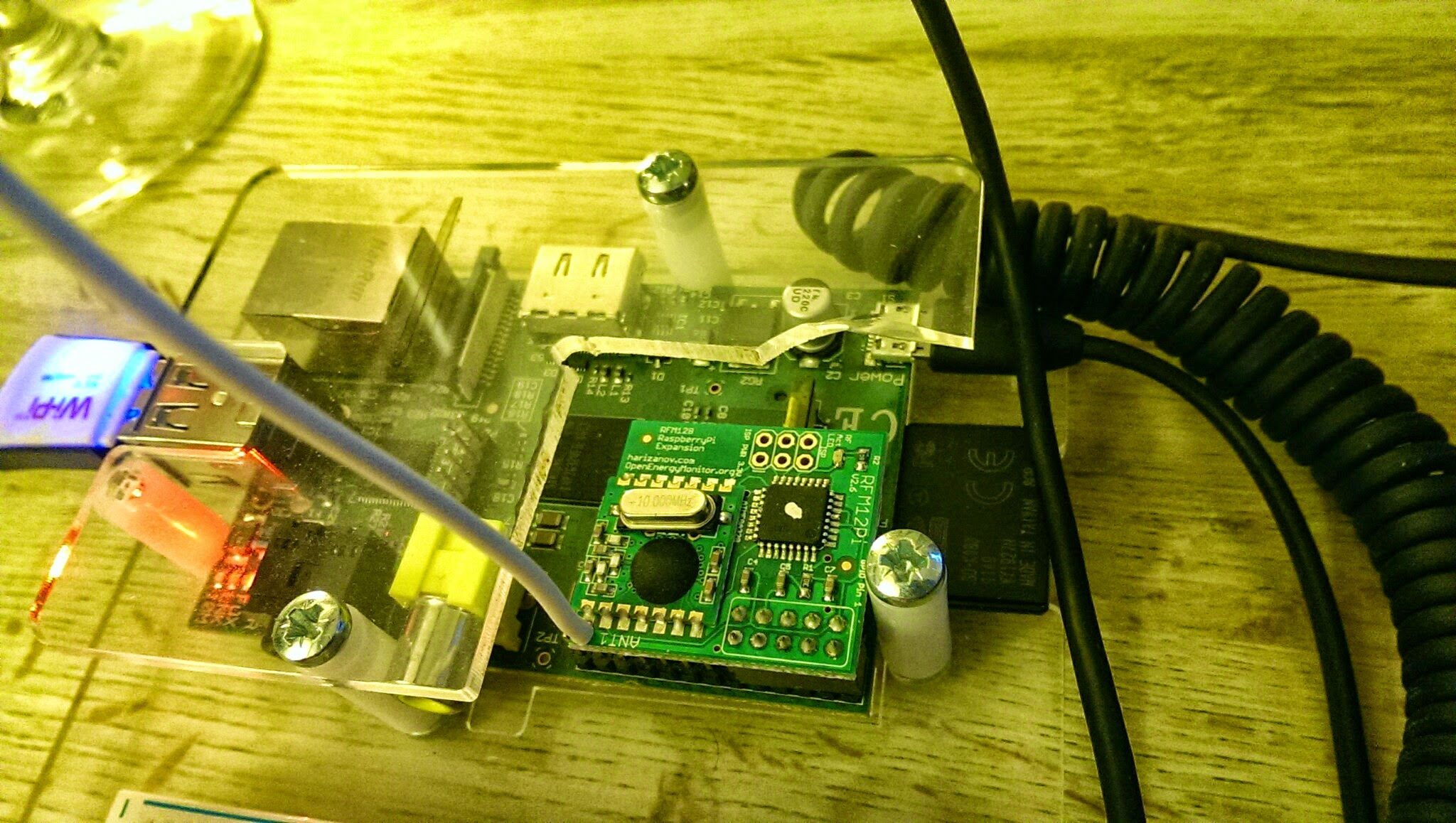
私が直面した最初の課題は、いくつかのMoteino(これらは素晴らしいです)を含む、低コストで既製のRFデバイスを評価することでした。これらはLowPowerLabs.comのFelix氏から提供され、OpenEnergyMonitorプロジェクトからのRFM12PiV2も含まれます。このデバイスはRaspberry Piに差し込み、すべてのRFベースのIOTデバイスへのインターネットゲートウェイとなります。
2つの異なるプロジェクトからRFデバイスを選んだため、それらが正しく通信できるようにいくつかの調整が必要です。これがこのブログの残りの部分でカバーする内容です。
これらのデバイスに共通しているのは、ATMega328チップに基づくArduino互換の開発プラットフォームを使用していることです。結果として、両方ともArduino IDEを使用してプログラムできます。また、これらのデバイスにはHopeRF RFM12Bトシーバーを含む統合されたダウターボードも備わっています。
異なる点は、それぞれ異なるプログラム(Arduinoの世界ではスケッチとも呼ばれます)を実行し、ハードウェアクロックもわずかに異なるアーキテクチャになっていることです。Moteinoは外部の16MHzクロック信号を使用するのに対し、RFM12PiV2はATMega328に内蔵された内部の8MHzクロックを使用します。この最後の情報は、デバイス間の送信を同期させる際に非常に重要です。
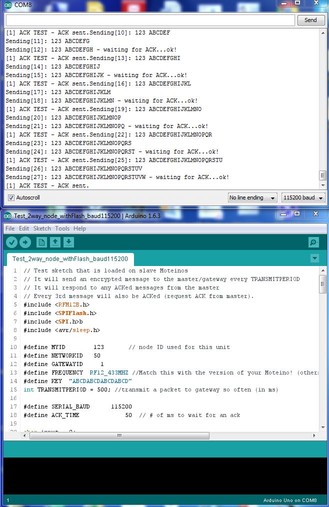
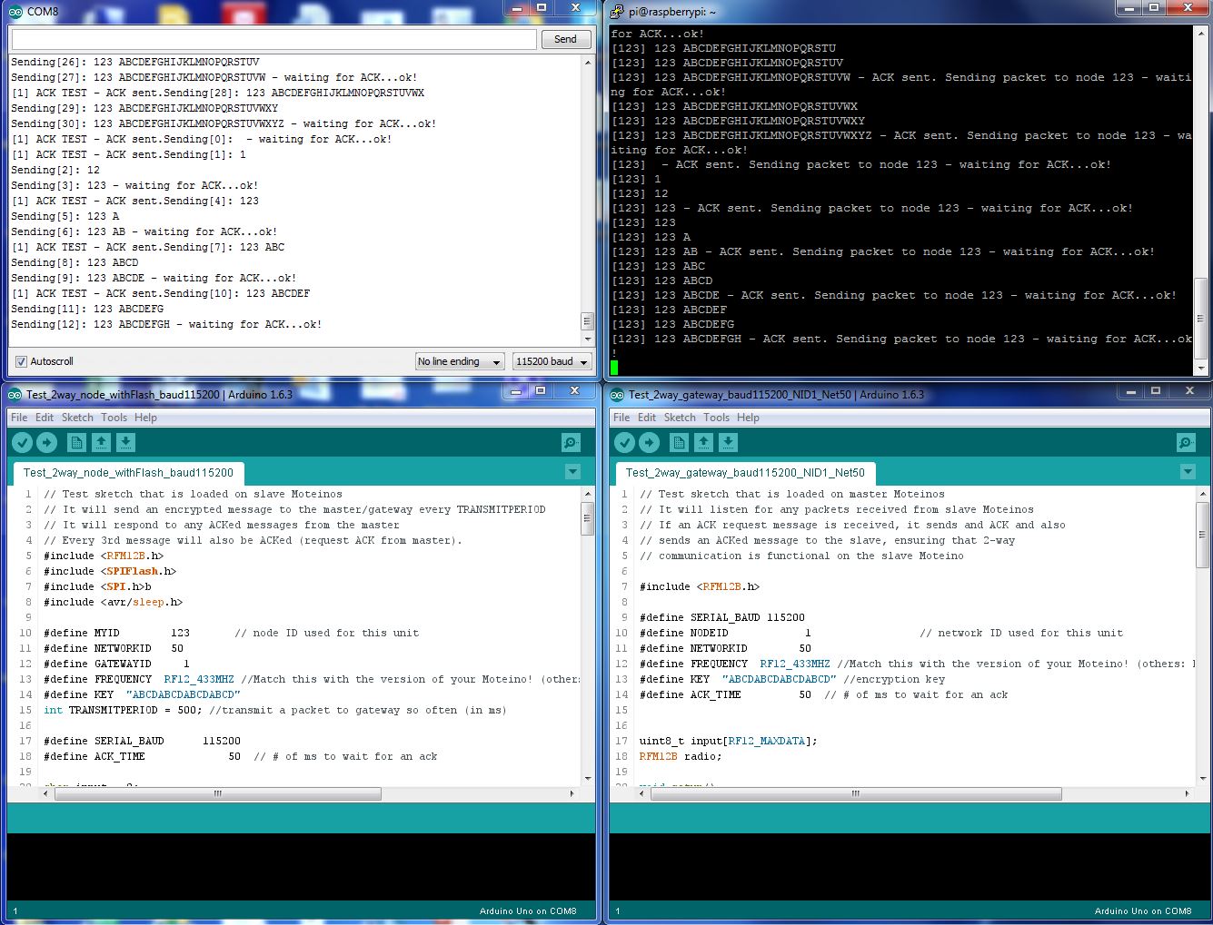
私は、ここで見つかるMoteinoのテストスケッチを使用することにしました – NodeとGatewayで、以下のようにアドレスとボーレートを少し変更するだけです:
ノードスケッチ
// Test sketch that is loaded on slave Moteinos
// It will send an encrypted message to the master/gateway every TRANSMITPERIOD
// It will respond to any ACKed messages from the master
// Every 3rd message will also be ACKed (request ACK from master).
#include <RFM12B.h>
#include <SPIFlash.h>
#include <SPI.h>b
#include <avr/sleep.h>

#define MYID 123 // node ID used for this unit
#define NETWORKID 50
#define GATEWAYID 1
#define FREQUENCY RF12_433MHZ //Match this with the version of your Moteino! (others: RF12_433MHZ, RF12_915MHZ)
#define KEY "ABCDABCDABCDABCD"
int TRANSMITPERIOD = 500; //transmit a packet to gateway so often (in ms)

#define SERIAL_BAUD 115200
#define ACK_TIME 50 // # of ms to wait for an ack

char input = 0;
RFM12B radio;
SPIFlash flash(8, 0xEF30); //EF30 for Windbond 4mbit flash
boolean requestACK = false;
byte sendSize=0;
char payload[] = "123 ABCDEFGHIJKLMNOPQRSTUVWXYZ";

void setup()
{
Serial.begin(SERIAL_BAUD);
radio.Initialize(MYID, FREQUENCY, NETWORKID, 0);
radio.Encrypt((byte*)KEY);
char buff[50];
sprintf(buff, "Transmitting at %d Mhz...", FREQUENCY == RF12_433MHZ ? 433 : FREQUENCY== RF12_868MHZ ? 868 : 915);
Serial.println(buff);
if (flash.initialize())
Serial.println("SPI Flash Init OK!");
else
Serial.println("SPI Flash Init FAIL! (is chip present?)");
}

long lastPeriod = -1;
void loop()
{
//process any serial input
if (Serial.available() > 0) {
input = Serial.read();
if (input >= 48 && input <= 57) //[0,9]
{
TRANSMITPERIOD = 100 * (input-48);
if (TRANSMITPERIOD == 0) TRANSMITPERIOD = 1000;
Serial.print("\nChanging delay to ");
Serial.print(TRANSMITPERIOD);
Serial.println("ms\n");
}
else if (input == 'd') //d=dump flash area
{
Serial.println("Flash content:");
int counter = 0;

while(counter<=256){
Serial.print(flash.readByte(counter++), HEX);
Serial.print('.');
}
while(flash.busy());
Serial.println();
}
else if (input == 'e')
{
Serial.print("Erasing Flash chip ... ");
flash.chipErase();
while(flash.busy());
Serial.println("DONE");
}
else if (input == 'i')
{
Serial.print("DeviceID: ");
Serial.println(flash.readDeviceId(), HEX);
}
}

//check for any received packets
if (radio.ReceiveComplete())
{
if (radio.CRCPass())
{
Serial.print('[');Serial.print(radio.GetSender(), DEC);Serial.print("] ");
for (byte i = 0; i < *radio.DataLen; i++)
Serial.print((char)radio.Data[i]);

if (radio.ACKRequested())
{
radio.SendACK();
Serial.print(" - ACK sent.");
}
Blink(9,5);
}
}

int currPeriod = millis()/TRANSMITPERIOD;
if (currPeriod != lastPeriod)
{
lastPeriod=currPeriod;
//Send data periodically to GATEWAY
Serial.print("Sending[");
Serial.print(sendSize);
Serial.print("]: ");
for(byte i = 0; i < sendSize; i++)
Serial.print((char)payload[i]);

requestACK = ((sendSize % 3) == 0); //request ACK every 3rd xmission
radio.Send(GATEWAYID, payload, sendSize, requestACK);
if (requestACK)
{
Serial.print(" - waiting for ACK...");
if (waitForAck(GATEWAYID)) Serial.print("ok!");
else Serial.print("nothing...");
}

sendSize = (sendSize + 1) % 31;
Serial.println();
Blink(9,5);
}
//else { Serial.print("currPeriod = "); Serial.print(currPeriod); Serial.print(" lastPeriod = "); Serial.println(lastPeriod); }
}

// wait a few milliseconds for proper ACK to me, return true if indeed received
static bool waitForAck(byte theNodeID) {
long now = millis();
while (millis() - now <= ACK_TIME) {
if (radio.ACKReceived(theNodeID))
return true;
}
return false;
}

void Blink(byte PIN, int DELAY_MS)
{
pinMode(PIN, OUTPUT);
digitalWrite(PIN,HIGH);
delay(DELAY_MS);
digitalWrite(PIN,LOW);
}
ゲートウェイスケッチ
// Test sketch that is loaded on master Moteinos
// It will listen for any packets received from slave Moteinos
// If an ACK request message is received, it sends and ACK and also
// sends an ACKed message to the slave, ensuring that 2-way
// communication is functional on the slave Moteino

#include <RFM12B.h>

#define SERIAL_BAUD 115200
#define NODEID 1 // network ID used for this unit
#define NETWORKID 50
#define FREQUENCY RF12_433MHZ //Match this with the version of your Moteino! (others: RF12_433MHZ, RF12_915MHZ)
#define KEY "ABCDABCDABCDABCD" //encryption key
#define ACK_TIME 50 // # of ms to wait for an ack
uint8_t input[RF12_MAXDATA];
RFM12B radio;

void setup()
{
pinMode(9, OUTPUT);
radio.Initialize(NODEID, FREQUENCY, NETWORKID);
radio.Encrypt((byte*)KEY);
Serial.begin(SERIAL_BAUD);
char buff[50];
sprintf(buff, "Listening at %d Mhz...", FREQUENCY == RF12_433MHZ ? 433 : FREQUENCY== RF12_868MHZ ? 868 : 915);
Serial.println(buff);
}

byte recvCount = 0;

void loop()
{
if (radio.ReceiveComplete())
{
if (radio.CRCPass())
{
digitalWrite(9,1);
Serial.print('[');Serial.print(radio.GetSender(), DEC);Serial.print("] ");
for (byte i = 0; i < *radio.DataLen; i++)
Serial.print((char)radio.Data[i]);

if (radio.ACKRequested())
{
byte theNodeID = radio.GetSender();
radio.SendACK();
//when a node requests an ACK, respond to the ACK and also send a packet requesting an ACK
//This way both TX/RX NODE functions are tested on 1 end at the GATEWAY
Serial.print(" - ACK sent. Sending packet to node ");
Serial.print(theNodeID);
delay(10);
radio.Send(theNodeID, "ACK TEST", 8, true);
Serial.print(" - waiting for ACK...");
if (waitForAck(theNodeID)) Serial.print("ok!");
else Serial.print("nothing...");
}
delay(5);
digitalWrite(9,0);
}
else Serial.print("BAD-CRC");

Serial.println();
}
}

// wait a few milliseconds for proper ACK to me, return true if indeed received
static bool waitForAck(byte theNodeID) {
long now = millis();
while (millis() - now <= ACK_TIME) {
if (radio.ACKReceived(theNodeID))
return true;
}
return false;
}
Moteinoへのスケッチのダウンロード
これは、Arduino IDEを実行しているPCにMoteinoを直接接続し、標準的なArduinoのプロセスを使用することで、 straightforward(簡単)に行うことができます。これらのデバイスには、非常に便利なワイヤレスプログラミング機能も備わっており、それについてはこちらで説明されています。
RFM12PiV2へのスケッチのダウンロード(Raspberry Piを使用)
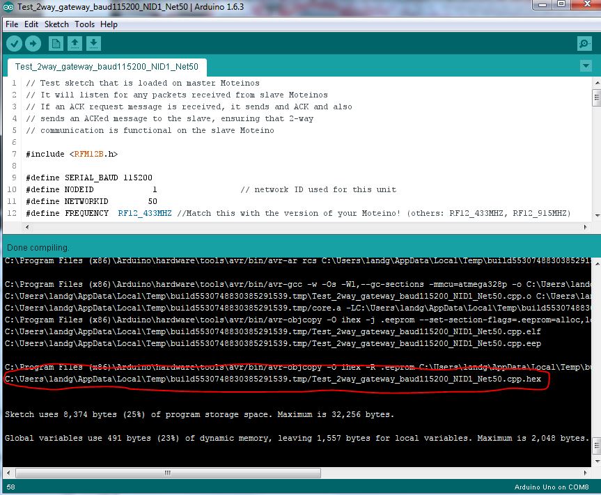
このプロセスは少しトリッキーです。まず、Arduino IDEを使用してゲートウェイスケッチをコンパイルし、次にコンパイルされたbinファイルの場所を確認する必要があります。
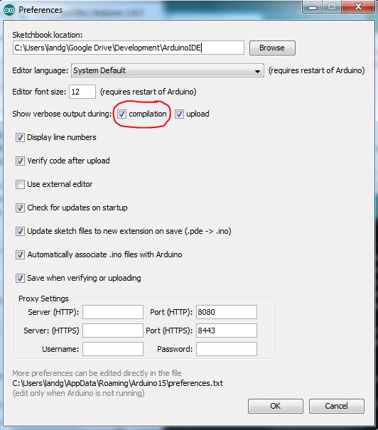
以下のように、Arduino IDEの設定で詳細出力を有効にします:
スケッチをコンパイルすると、出力ウィンドウに、Raspberry Piに転送する必要があるコンパイル済みファイルの場所が表示されます。
こちらで詳述されているように、Raspberry Piのシリアルポートが有効になっていることを確認してください。
このパズルの最後のピース – Raspberry PiからRFM12PiV2に新しいコードをアップロードする方法 – はすでにこちらで文書化されていますが、以下でも再度概説します:
$ sudo apt-get update
$ sudo apt-get install -y arduino python-dev python-rpi.gpio
$ git clone https://github.com/mharizanov/avrdude-rpi.git
$ cd avrdude-rpi
$ sudo cp autoreset /usr/bin
$ sudo cp avrdude-autoreset /usr/bin
$ sudo mv /usr/bin/avrdude /usr/bin/avrdude-original
$ sudo ln -s /usr/bin/avrdude-autoreset /usr/bin/avrdude
# Change to the directory where the binary file has been copied
$ avrdude -v  -c arduino -p ATMEGA328P -P /dev/ttyAMA0 -b 38400 -U flash:w:<Enter Filename Here and remove arrow brackets>
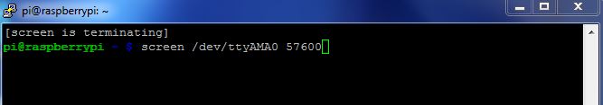
最後に、お好みのツールを使用してRaspberry Piのシリアルポートを読み取ります – 私はscreenを選択しました。長期的にはPythonスクリプトを使用する予定です。
注意 クロック速度の違いを覚えておいてください – これが今、役立ちます。スケッチの両方でボーレートが115200に設定されているにもかかわらず、クロック速度が半分(16MHzではなく8MHz)で動作しているRFM12PiV2に接続する場合、ボーレートを115200ではなく57600に設定する必要があります。
すると、以下のようなものが見えるはずです
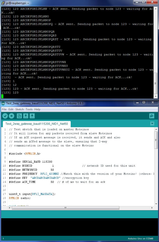
すべてを組み合わせると、動作するMoteinoからRFM12PiV2への基本通信システムが完成します。
タァー – ダァー!
残念ながら、RFM12Bモジュールはすでに生産終了となったようです。なので、RFM69でこれをすべてやり直す必要があります。あるいは、こちらを試してみるかもしれません
🙂
Originally published on allthingscloud.eu (2015-04-26).